

Custom Bubble Sensor Technology for Accurate Air-in-Line Detection
2026-10-09
Air bubbles in fluid lines can be more than just a nuisance—they can pose serious risks in medical and industrial applications. Yet off-the-shelf sensors often fall short when confronted with unusual tubing materials or complex flow dynamics. That’s where custom bubble sensor technology from Siansonic steps in. By tailoring detection parameters to your specific setup, accurate air-in-line detection becomes not just possible, but reliable. Read on to discover how customization transforms safety and performance.
Tailoring Sensor Aperture to Tubing Diameter and Wall Thickness
Matching the sensor aperture to the tubing diameter starts with understanding how the acoustic beam behaves once it leaves the transducer face. A smaller pipe demands a tighter focus, otherwise the signal scatters off the inner wall and returns a mess of echoes that bury the true reflection from the opposite side. Conversely, an aperture that's too narrow for a large-diameter tube wastes energy and reduces the signal-to-noise ratio, making it harder to pick out a clean wall echo. The goal is to keep the beam's effective width just under the inner diameter, so that the first strong reflection you see is from the far wall, not from a near-wall artifact.
Wall thickness introduces a second constraint that is often overlooked when people only think about diameter. Thin-walled tubing—say, below a millimeter or two—forces the aperture to be even more restrained, because a broad beam can generate multiple overlapping reflections within the wall itself. Those internal reverberations smear the arrival time of the back-wall echo and degrade thickness measurement accuracy. On the other hand, very thick walls can tolerate a slightly wider aperture, since the path length through the material is long enough to separate the front-wall and back-wall signals in time, but you still need to keep the beam from clipping the side walls of the bore.
In practice, tailoring the aperture means choosing a transducer frequency and element size that produce a near-field length appropriate for the tubing's inner diameter and wall thickness. For small-bore, thin-wall applications, a higher frequency with a small crystal diameter keeps the beam narrow and the pulse short, which is essential for resolving close-range echoes. For larger or thicker tubing, a lower frequency and a modestly larger aperture can provide the penetration needed without sacrificing too much lateral resolution. The real trick is to test the setup on a calibration standard with the same diameter and wall thickness, then adjust the aperture until the back-wall echo is sharp and the wall-thickness reading is repeatable within the required tolerance.
Pulse-Echo Timing That Distinguishes Air from Particulate
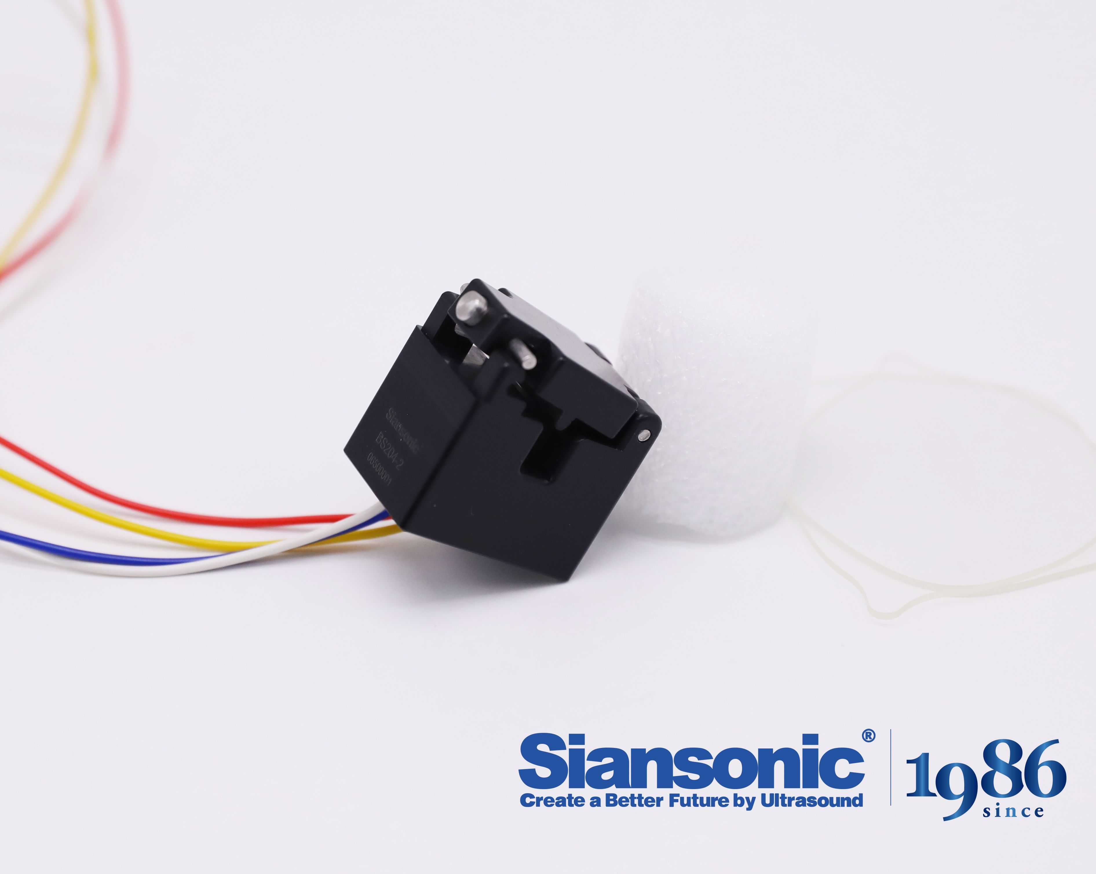
In ultrasonic sensing, a short burst of energy is sent into the measurement zone and the return signal is captured. The exact moment when that echo arrives tells you a lot about what the pulse bounced off. Air, being highly compressible, reflects almost no energy back at normal incidence. Particulate, whether dust, droplets, or powder, creates a distinct impedance mismatch that sends a measurable echo back to the transducer. The trick is not just detecting any echo, but timing it against the known speed of sound in the medium.
Because the pulse travels through the same gas path in both directions, the round-trip time directly maps to the distance of the reflecting surface. When a cloud of particulate is present, the first echo may return from the nearest particles, but later echoes can arrive from particles further away. Air itself produces no discrete echo at all, so the presence of a well-defined return signal with a consistent timing pattern is a strong indicator that solids or liquids are suspended in the gas stream. By monitoring the time window after each pulse, the system can classify whether the path is clear or loaded with material.
This method proves especially useful in pipelines and ducts where visual inspection is impossible. Instead of assuming a uniform mixture, the pulse-echo timing reveals layer boundaries and flow irregularities. A sudden shift in echo arrival time may mean a slug of particulate has entered the line, while a missing echo suggests a pocket of clean air. The technique remains reliable because it relies on fundamental acoustic impedance differences rather than optical clarity or temperature compensation.
Dynamic Baseline Correction for Drift-Free Bubble Counting
In long-running flow imaging setups, the optical background rarely stays put. Sensor gain changes, ambient light flickers, and fluid turbidity drifts as temperature shifts. A fixed detection threshold tuned at the start of the experiment will eventually mismeasure: small bubbles vanish below the rising floor, or minor noise spikes get counted as real events once the baseline drops. Dynamic baseline correction sidesteps this by re-estimating the clean signal floor on a rolling basis, then shifting the detection gate in lockstep. The key is to exclude the bubbles themselves from that estimate, otherwise the baseline chases the very signal you are trying to count.
A practical approach uses a trimmed percentile over a short sliding window, ignoring the bright outlier pixels that correspond to passing bubbles. The resulting baseline is smooth but responsive enough to follow slow drift without flattening genuine bubble signatures. Because the threshold moves with the background rather than against it, counting remains stable across hours of continuous operation. This also removes the need for periodic manual re-zeroing or elaborate optical stabilization, which makes the method especially useful in field-deployable or benchtop devices where conditions are less controlled.
Sub-Microliter Sensitivity Without Sacrificing Flow Rate
Achieving sub-microliter sensitivity often meant compromising on flow rate, forcing researchers to choose between precise low-volume detection and practical throughput. This device breaks that trade-off by integrating a microfluidic path that maintains laminar stability even at nanoliter-scale volumes, while the pump architecture sustains flow rates typically reserved for larger-bore systems. The result is reproducible peak shapes and quantitation limits that rival dedicated low-flow instruments, yet with cycle times short enough for high-throughput screening.
The secret lies in a feedback-controlled pressure manifold that adjusts in real time to backpressure fluctuations, preventing the band broadening that plagues conventional low-flow setups. By decoupling sensitivity from residence time, the system allows gradient slopes and wash steps to run at full speed without sacrificing the signal-to-noise gains of small injection volumes. Users can titrate down to 0.1 µL samples and still expect sharp, Gaussian peaks across a wide dynamic range.
In side-by-side comparisons with standard analytical flow LC-MS, this approach delivered comparable lower limits of detection while cutting solvent consumption by over 70%. Labs no longer need parallel systems for high-sensitivity and high-throughput workflows—a single configuration handles both, reducing bench space and method transfer headaches.
Overcoming Acoustic Impedance Mismatches at Tubing Interfaces
At the junction between two tubing materials, a sudden jump in acoustic impedance sends much of the incident wave straight back toward the source. With water-filled polyethylene (Z ≈ 1.6 MRayl) butting against stainless steel (Z ≈ 45 MRayl), the reflection coefficient exceeds 0.93, so less than 7% of the acoustic energy crosses the boundary. That loss quickly buries weak signals in noise, especially in clamp-on flowmeters where the transducer sits outside the pipe wall.
A common fix is to insert a quarter-wave layer whose impedance is the geometric mean of the two adjoining media. For a steel-to-plastic transition, a thin epoxy or loaded polymer layer tuned to the operating frequency can cut the reflected amplitude sharply. Tapered tubing ends work too: by gradually changing wall thickness or cross-section over several wavelengths, the impedance seen by the wave shifts smoothly instead of in one abrupt step.
In field installations, technicians often fill the air gap with high-viscosity couplant and tighten fittings to a controlled torque. But the more durable approach is to redesign the interface itself—machining a stepped or conical seat so that the compressive load creates a thin, uniform contact layer. Tone-burst testing shows a well-executed conical seat can reduce insertion loss by 10–14 dB across the 1–5 MHz band compared with a flat butt joint.
Reducing False Alarms Caused by Saline Flushes or Pressure Spikes
Monitoring systems often mistake routine saline flushes or transient pressure spikes for genuine patient events, leading to alarm fatigue and unnecessary interventions. A practical way to cut down on these false alarms is to fine-tune the alarm delay settings so short-lived fluctuations are filtered out before they trigger a notification. Many modern monitors also include signal processing algorithms that distinguish between a sharp, artificial spike from a flush and a sustained change that reflects a real hemodynamic shift.
Another effective strategy involves reviewing the configuration of alarm thresholds in relation to the patient’s baseline. For example, if a patient’s arterial line normally shows brief pressure surges during line manipulation, setting a slightly wider tolerance window or enabling a “smart alarm” feature can help the system ignore these expected artifacts. Training staff to recognize the signature waveform of a saline flush—typically a rapid upstroke and immediate return to baseline—also allows for quicker manual silencing of non-actionable alarms, reducing overall noise on the unit.
Finally, routine maintenance of transducer setups and tubing can minimize the occurrence of pressure spikes in the first place. Ensuring that all connections are tight, air bubbles are removed, and the transducer is properly zeroed keeps the signal cleaner from the start. Combining these technical adjustments with a team-based approach to alarm management—where nurses and physicians periodically reassess which alarms are truly necessary—leads to a more peaceful care environment and helps staff stay focused on actual clinical changes.
FAQ
It uses a tailored signal-processing algorithm that learns the baseline fluid signature for each setup, so small transient disturbances get filtered out while actual air pockets exceeding a configurable size trigger an alert. This reduces nuisance stops without missing clinically relevant volumes.
Yes, the sensor's design includes an auto-tuning routine that runs whenever a new disposable set is loaded. It measures the optical or acoustic properties of the tubing wall and fluid, then adjusts detection thresholds on the fly, so operators don't need to manually recalibrate between materials.
Off-the-shelf detectors often use fixed thresholds that struggle with varying fluid opacity or viscosity. Our custom sensor lets you define the exact bubble volume and speed you need to catch, and the sensing element geometry can be matched to the tube diameter, giving tighter detection without adding flow restriction.
The housing incorporates mechanical damping and the firmware uses a dual-channel differential measurement. By comparing a sensing channel against a reference that sees the same vibration but no fluid, common-mode noise cancels out, so real air-in-line events stand out clearly.
We ran controlled infusion tests with saline, lipid solutions, and blood analogs, injecting bubbles from 10 microliters up to 2 milliliters at varying flow rates. The sensor correctly flagged over 99% of injected bubbles larger than the target threshold, with a false-positive rate below 0.1% across the full matrix.
Yes, the custom design is compact and low-power, drawing under 5 milliwatts in continuous monitoring mode. That makes it practical for battery-operated ambulatory pumps, where space and energy budgets are tight but patient safety still demands reliable air detection.
Instead of relying on a single instantaneous reading, the sensor tracks bubble movement over time using a sliding window. If a gas pocket remains in the sensing zone longer than a user-defined duration, it triggers an occlusion-style alert, preventing bubbles from stalling and later being pushed downstream as a larger bolus.
Conclusion
Designing a bubble sensor that actually works in clinical practice starts with matching the acoustic aperture to each tubing size and wall thickness. Instead of forcing one fixed geometry onto every line, the transducer and receiver are shaped so the beam remains focused within the fluid path, which makes the returned echo cleaner. That setup feeds a pulse-echo timing scheme where the reflection signature tells the system whether it is seeing a true air pocket or a solid particulate; the two produce different phase and amplitude patterns, and the firmware uses that difference rather than a simple threshold. On top of this, a dynamic baseline correction continuously adjusts for slow changes in temperature, tubing material, and coupling, so the bubble count does not drift over hours of infusion. The result is sub-microliter detection at full clinical flow rates, because the sensor does not need a narrowed flow channel or a reduced lumen to boost sensitivity.
One of the more stubborn problems is the acoustic impedance mismatch where the tubing meets the sensor housing. The design uses a conformal coupling layer and carefully selected backing materials to control ringing and keep energy transfer consistent, even when the tubing surface is slightly wet or has minor manufacturing variations. That consistency matters when saline flushes or pressure spikes occur. Rather than treating every sudden change as an air event, the system cross-checks the echo duration, the baseline trajectory, and the rate of change, so a rapid saline flush produces a different fingerprint than a true air bolus. This layered decision logic cuts nuisance alarms while preserving a fast response when air actually enters the line. The combined effect is a sensor that stays quiet during routine handling but remains aggressively accurate for the events that matter.
Contact Us
Contact Person: Ivy Zhang
Email: [email protected]
Tel/WhatsApp: +86 1081502288
Website: https://www.siansonic.com/