

ODM Louver Damper Valve Solutions for Industrial Airflow Control
2026-09-30
Getting airflow wrong in an industrial line doesn’t just waste energy—it can quietly eat into product quality and worker safety. Yet many facilities still settle for off-the-shelf dampers that never quite match their ductwork, pressure drops, or control sequences. That’s where THT comes in. Our ODM louver damper valve solutions are built around your actual process, not a catalog spec, giving you tighter modulation, lower leakage, and a system that finally behaves the way it should.
Why Generic Dampers Struggle with Industrial Airflow Variability
Industrial airflow rarely behaves like the steady, uniform stream assumed in catalog specifications. In real plants, dampers face sudden velocity spikes, temperature swings, and uneven pressure profiles caused by batch processes, filter loading, or upstream equipment cycling. Generic dampers are built around a narrow operating window, so when airflow becomes chaotic, their blades flutter, seals wear unevenly, and actuators hunt for a stable position. This mismatch shows up quickly as control drift, leakage through closed blades, and premature bearing fatigue—all of which force maintenance teams into reactive repairs rather than planned upkeep.
The core issue is that generic designs prioritize cost and simplicity over adaptation to variable flow regimes. Their blade profiles create turbulence at off-design angles, and standard linkage systems amplify any play or flex under fluctuating torque. In contrast, dampers engineered for industrial variability use reinforced structures, low-friction bushings, and aerodynamic blade shapes that maintain sealing force even when flow direction or velocity shifts abruptly. Without these features, a damper may work fine on a test bench but degrade rapidly in a live duct system where airflow is never static.
Another struggle comes from instrumentation and control assumptions. Generic dampers often ship with actuators sized for average torque only, ignoring peak loads during surge conditions or the need for fast partial-stroke response. When the process demands precise modulation across a wide range—say 10% to 90% open—a generic damper’s flow characteristic curve becomes unpredictable, making it hard to tune the loop. Over time, operators lose confidence in the damper’s ability to hold a setpoint, leading to manual bypasses, wasted energy, and inconsistent product quality.
Tailoring Blade Profiles for Non-Linear Flow Requirements
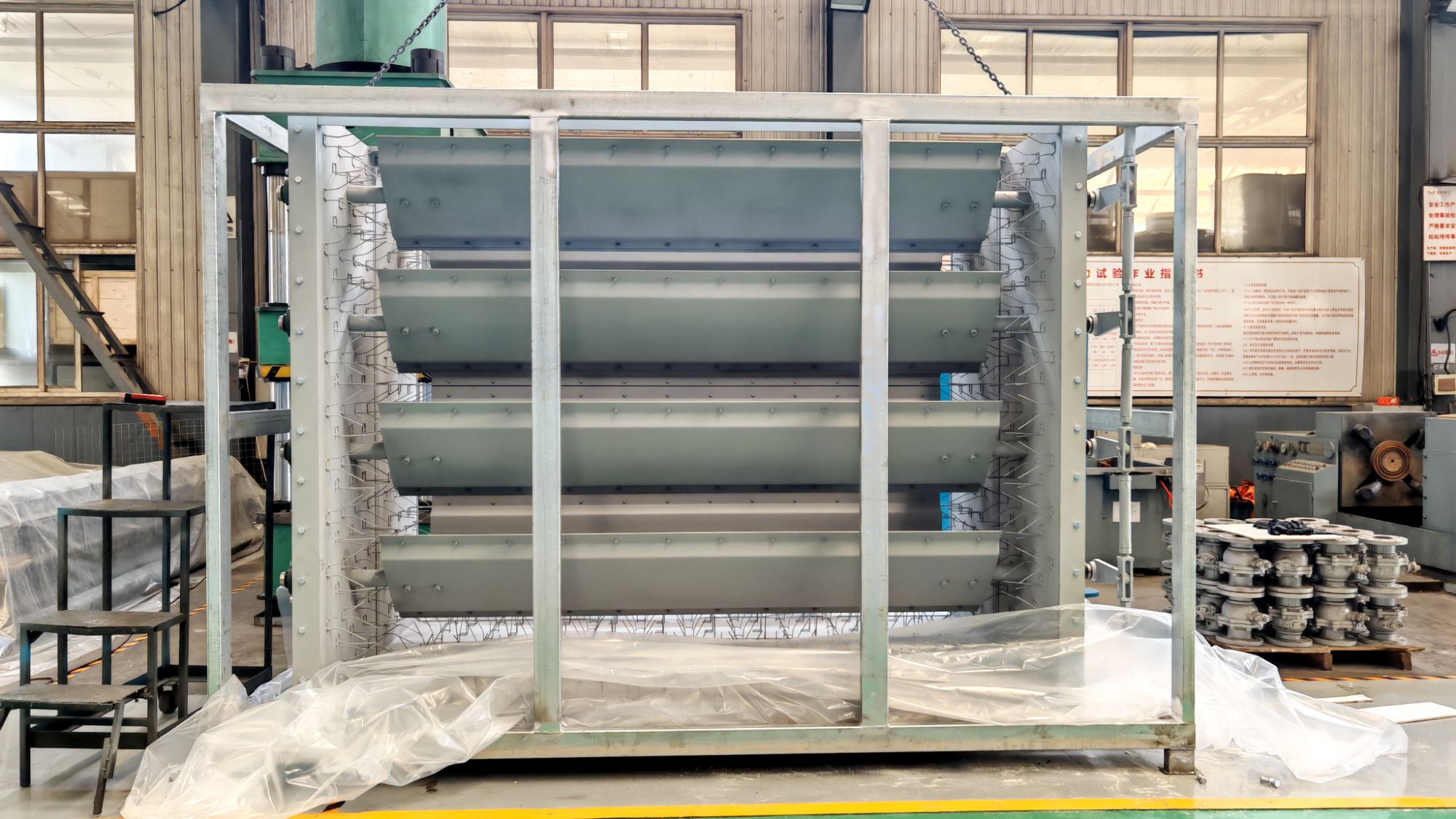
Flow around a blade rarely stays attached or behaves linearly across the full operating range. At high loading, local acceleration around the leading edge can push the suction side toward separation, while at off-design incidence the stagnation point shifts and secondary flows intensify. A profile optimized only for a single design point tends to overreact to these changes, so tailoring must account for the shape of the loss bucket rather than a single pressure distribution.
Instead of simply adding camber to raise turning, the curvature is often redistributed further aft, which keeps the leading edge less sensitive to incidence variation. A slightly blunter nose with a carefully controlled thickness gradient can delay leading-edge separation without giving up much peak efficiency, and a thinner trailing edge region reduces base drag as the boundary layer thickens under adverse pressure gradients. The resulting profile lets loading shift gradually with flow coefficient rather than collapse abruptly.
Wind tunnel traverses and unsteady pressure measurements usually reveal where the linear assumptions break down. Checking for hysteresis in pressure recovery or sudden changes in deviation angle helps pinpoint the geometric parameters that matter most for non-linear behavior. That kind of targeted reshaping tends to widen the stable operating range with fewer compromises than applying a uniform scale factor to a standard blade section.
Sealing Systems That Hold Up Under Thermal Cycling
Thermal cycling punishes seals in ways that steady-state heat never does. Every swing from hot to cold forces the material to expand and contract, and any mismatch between the seal, the mating flanges, and the housing quickly turns into a leak path. Designs that survive this environment usually abandon rigid, one-size-fits-all profiles in favor of controlled flexure zones—thin lips, bellows features, or spring-energized jackets that let the seal breathe without losing contact pressure.
Material choice matters just as much as geometry. Filled PTFE compounds with carefully selected additives maintain creep resistance through repeated temperature excursions, while high-performance elastomers like perfluoroelastomers hold elasticity at both ends of the cycle. What often gets overlooked is the groove design: a seal that works at room temperature can extrude or stick-slip after a few hundred cycles if the groove doesn't account for thermal expansion of the surrounding metal. Adding a slight axial clearance or a backup ring in the right spot often makes the difference between a seal that lasts years and one that fails in a weekend.
Testing is where these systems prove out. Lab fixtures that cycle from cryogenic temperatures to several hundred degrees in minutes expose weak points that static certifications miss. The most reliable seals don't just survive a set number of cycles—they show predictable, repeatable recovery after each excursion, with no progressive loss of sealing force. That kind of data gives engineers a realistic margin instead of a hopeful guess.
Choosing the Right Actuator for High-Cycle Duty
High-cycle applications punish actuators in ways that low-duty systems never will. Every start, stop, and reversal adds stress to bearings, seals, and drive components, so the first decision is not about force or speed but about endurance. Look for actuators with hardened raceways, oversized thrust bearings, and lubrication pathways designed for continuous operation. If the duty cycle exceeds 500,000 cycles per year, traditional ball screw actuators may need to be replaced with roller screw or belt-driven designs that distribute load more evenly and keep heat generation in check.
Beyond mechanical wear, control precision matters just as much. An actuator that holds position well under intermittent use can drift or overshoot when cycled every few seconds. Closed-loop feedback with high-resolution encoders becomes non-negotiable, along with motor windings rated for frequent starts without thermal derating. In many cases, pairing the actuator with a servo drive that supports jerk limiting and adaptive tuning prevents the shock loads that shorten component life in high-cycle scenarios.
Finally, look past the catalog torque curve and ask for actual cycle test data. Manufacturers often quote rated life at 30% duty, but high-cycle duty demands 70% or more. Field failures from worn seals, cracked couplings, or loosened mounting bolts are rarely visible in static specifications. Choosing the right actuator means balancing initial cost against the cost of unplanned downtime, and in high-cycle environments, a modest premium for a hardened, well-instrumented unit pays for itself within the first year of continuous operation.
Field-Repairable Designs That Cut Downtime
When a hydraulic manifold on a mining haul truck cracks at 2 a.m., the difference between a two-hour fix and a two-day teardown comes down to how the original engineers laid out the component. Field-repairable design isn't about slapping on quick-release fasteners; it's about anticipating where failures actually occur and making those spots reachable with standard tools, in the dark, while wearing thick gloves. For example, routing a critical sensor wire through a protected channel that can be unclipped and replaced without removing the entire engine control harness saves hours of tracing and splicing. The goal is to shrink the repair envelope to the smallest possible physical and procedural footprint.
Downtime in heavy equipment or industrial machinery rarely stems from a single complex failure—it's the cascade of small access problems. A field-repairable design front-loads the dismantling sequence: placing the most failure-prone parts (seals, filters, wear plates, electrical connectors) on the outermost layer of an assembly, not buried behind three staged covers. One construction equipment manufacturer cut hydraulic pump swap time from 6.5 hours to 40 minutes by redesigning the mount so the pump could be unbolted from the side, without draining the reservoir or removing the radiator. That kind of change doesn't show up on a spec sheet, but it directly reduces the mean time to repair in a muddy jobsite.
The real test of a field-repairable design is whether a technician can diagnose and fix the issue with the tools already in the service truck. Modular subassemblies with alignment pins and captive fasteners prevent lost bolts and misaligned reinstallation. Color-coded, oversized drain ports with built-in sediment traps let operators clear blockages without disconnecting hydraulic lines. And a clearly marked test point manifold—placed where a pressure gauge can be threaded in without removing guards—turns a frustrating guessing game into a ten-minute verification. These choices aren't glamorous, but they compound across a fleet: every avoided hour of downtime is another hour of production, and that's the only metric that matters at the end of a shift.
Testing Beyond Spec Sheets: Real-World Leakage and Torque Validation
A spec sheet will tell you a valve seals at 150 psi in a controlled lab, but it says nothing about what happens after six months of thermal cycling on a steam line. Real-world leakage rarely shows up as a sudden burst—it starts as a faint hiss, a damp spot on insulation, or a drift in pressure that maintenance crews chase for weeks. We stopped trusting catalog numbers after a batch of flanged ball valves passed every factory hydro test, only to weep at the stem packing once installed in a chilled water system running at 38°F. The issue wasn't the seat; it was the packing material contracting faster than the bonnet, opening a hairline path no bench test ever saw.
Leakage validation outside the lab means isolating variables that specs ignore: vibration from nearby pumps, pipe misalignment, and the slow creep of gasket relaxation. We now run our own field tests with helium mass spectrometers on live systems, not just air under water. One gate valve on a condensate return looked bone dry during a 30-minute soap bubble check, but a helium sniffer picked up 4×10⁻⁶ mbar·L/s at the gland—barely above background, yet enough to corrode the stem threads over a winter. That kind of data doesn't come from a datasheet; it comes from walking the line at 2 a.m. with a probe and a notepad.
Torque validation is just as slippery. A manufacturer's torque chart assumes clean threads, perfect lubrication, and a new gasket. Throw in some rust, a reused spiral-wound gasket, and a pipefitter who "feels" the bolt is tight enough, and you're off by 30% or more. We started using ultrasonic bolt meters on critical flanges after a heat exchanger blew a gasket at only 60% of the specified seating stress. The bolts had been torqued in a star pattern, but the gasket had uneven compression because two studs were slightly bent from a previous over-tightening. Now every high-pressure joint gets a before-and-after torque signature, not just a final click from a wrench.
FAQ
They are custom-designed modulation devices that use adjustable blades to regulate, isolate, or redirect air or gas streams. The blade angle is controlled manually or via actuators, allowing precise pressure and flow adjustments in ducts or process lines.
Power generation, cement, steel, petrochemical, and HVAC sectors are common. Any facility with large ducts, high temperatures, or aggressive gas streams can benefit from tailored damper designs.
Instead of forcing a generic part into a specific ductwork, the original design manufacturer shapes the frame, blade profile, sealing system, and materials around actual operating data such as temperature swings, pressure differentials, particulate load, and corrosion risk.
Carbon steel, stainless grades like 304 and 316, and specialized alloys such as Corten or Inconel are common. Material choice depends on temperature, chemical exposure, and abrasion. High-temperature applications may also use refractory-lined blades.
Yes, but the internal design differs. Isolation dampers prioritize tight shut-off with seal arrangements and low leakage classes, while modulation dampers focus on linear control response and resistance to flutter across a range of blade angles.
Manual gearboxes, electric multi-turn actuators, pneumatic cylinders, and hydraulic drives can all be integrated. The actuator is sized based on torque requirements from blade area, differential pressure, and expected fouling.
Seal selection matters more than blade strength. We often use metallic leaf seals, Inconel brush seals, or air-purged seats to handle thermal expansion and dust accumulation without jamming or excessive leakage.
Duct dimensions, gas composition, temperature range, pressure drop limits, required leakage class, actuator preference, and any space constraints. With that data, the design can be optimized rather than simply adapted.
Conclusion
Standard damper assemblies rarely survive long in plants where airflow swings from low-volume trickle to full-open surge within a single shift. Generic blade shapes assume a linear relationship between angle and flow, but real processes often demand non-linear response curves, especially when balancing multiple branches or protecting downstream equipment from pressure spikes. ODM louver damper valve work starts by mapping actual velocity profiles and turbulence zones across the duct, then shaping each blade chord, edge radius, and overlap angle to deliver the required resistance at specific positions. The result is a damper that modulates smoothly instead of hunting or fluttering. Equally important is the sealing system. Thermal cycling can loosen bolted seats and crush soft gaskets, turning a supposed tight-shut damper into a leak path. ODM designs often use spring-loaded metal leaf seals or graphite-impregnated composite strips that maintain contact as duct walls expand and contract. This keeps leakage within predictable limits without requiring frequent manual retorquing.
Actuator selection rarely gets enough attention until a damper fails mid-cycle. For high-cycle duty, direct-coupled electric actuators with continuous modulation ratings outlast standard on-off models, but pneumatic or electro-hydraulic options may make more sense when fail-safe positioning or high torque at low speeds is required. ODM suppliers match actuator inertia, speed, and torque curve to the actual blade load rather than relying on a generic safety factor. They also design for repair in place. Removable blade segments, split shafts, and accessible bearing blocks allow maintenance crews to replace worn components without removing the entire frame from the duct—a major advantage when downtime is measured in lost production hours. Finally, validation goes beyond catalog leakage rates. Prototype dampers are mounted on test stands that reproduce the plant's real velocity range, temperature swings, and duct deformation. Torque is measured at multiple blade angles under both clean and particulate-laden airflow, and leakage is checked with thermal imaging and tracer gas, not just cold air pressure drop. This level of testing catches problems that spec sheets miss and gives plant engineers confidence that the damper will hold its performance after years of thermal and mechanical fatigue.
Contact Us
Contact Person: Su Zhang
Email: [email protected]
Tel/WhatsApp: +86-25219206
Website: https://www.tht-valve.com/