

Substantial Oil-Immersed Transformer Fundamentals Every Engineer Must Know
2026-08-22
Most engineers can read a transformer nameplate, but few can explain the thermal and dielectric stresses that determine whether a substantial oil-immersed unit survives past its warranty—let alone thirty years. That gap gets expensive fast. Chang Song has spent years closing it, and this guide distills the fundamentals every engineer should know before the next specification, test, or failure investigation lands on your desk.
Why Oil Does More Than Cool the Windings
You might think of oil as just a coolant, but that's only part of the story. While it does carry heat away from the windings, its role as an electrical insulator is equally critical. The oil fills every gap and pore between conductors, raising the dielectric strength of the entire assembly and preventing arcing that would otherwise occur at high voltages.
Beyond insulation, oil also acts as a shock absorber for electrical stress. During a fault or switching surge, the oil absorbs and dissipates the energy of an arc, quenching it before it can damage the windings or the tank. This protective function is why oil-filled equipment can often survive transient events that would destroy dry-type alternatives.
Then there's the quieter work oil does over the long haul. It forms a barrier against moisture and oxygen, slowing corrosion on the copper and core steel. At the same time, it dampens vibration and noise, which reduces mechanical fatigue. So while cooling matters, it's really just one chapter in a much longer list of duties.
Reading a Dissolved Gas Report Without Panic
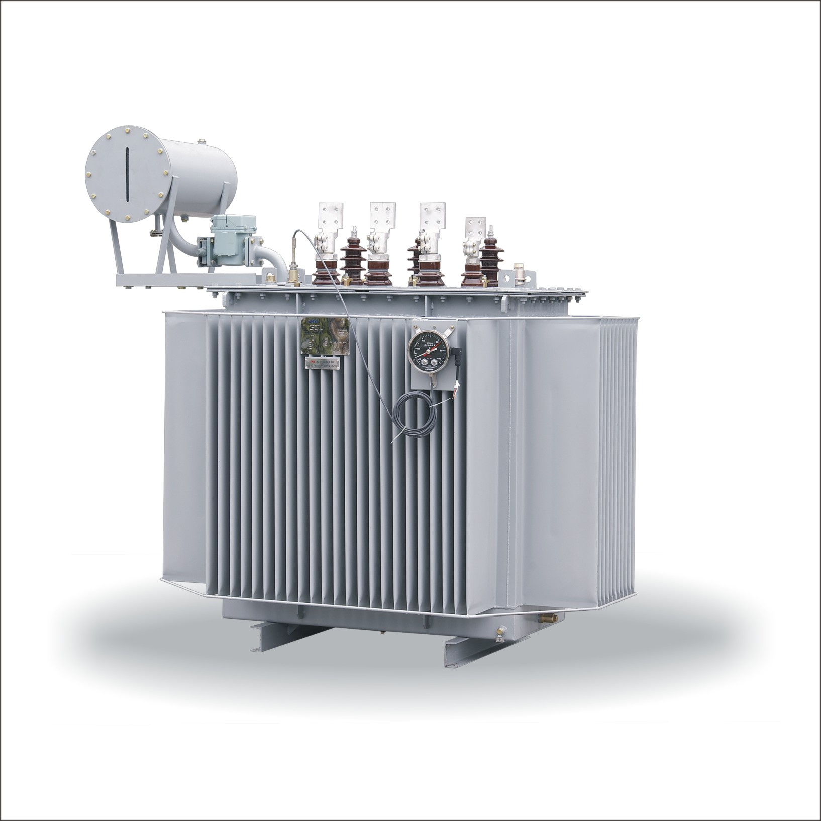
Receiving a dissolved gas report can feel like opening a medical scan without a doctor nearby—every number seems to demand immediate alarm. Yet most reports are simply early whispers, not shouts. The first step is to stop treating the data as a verdict. Compare the latest values against the equipment's own history. A single spike often means a passing disturbance: a recent overload, a brief hot spot, or even a sampling quirk. Panic usually comes from reading one snapshot as if it were the whole film.
Instead of trying to memorize every threshold, focus on ratios and trends. Look at how key gases like hydrogen, methane, ethylene, and acetylene relate to one another. A slow rise in methane with low acetylene suggests normal aging or mild overheating. But if acetylene appears suddenly and keeps climbing, that's your cue to investigate arcing or sparking. Think of it as reading a weather chart—you don't panic at a single cloud, but you do notice when dark fronts start stacking in the same corner.
When something does look off, resist the urge to fire off frantic emails or order an immediate shutdown. Bring the report to your maintenance team the way you'd bring a puzzling noise from your car to a mechanic: describe the pattern, note any recent operational changes, and ask for a targeted follow-up. Often the next step is simply resampling in a few weeks or checking a sensor. Calm, scheduled attention beats reactive fear every time.
Core and Coil Geometry: The Real Source of Hot Spots
Most thermal models blame overloads or poor ventilation for hot spots, but the actual culprit often hides in the physical arrangement of the core and coils. When windings bunch too tightly around a core leg, or leave uneven gaps between layers, heat builds exactly where magnetic flux density and current crowding coincide. A winding that looks symmetrical on a drawing can still create a narrow thermal neck if the innermost turns sit closer to the core than the outer ones, starving that region of cooling oil or air flow. Designers who only check average temperature rise miss these local extremes until insulation ages prematurely or a turn-to-turn fault appears.
Geometric quirks like a core with uneven limb cross-sections, a coil shifted off-center during assembly, or an interlayer duct that pinches closed under clamping pressure all shift the heat map in ways a uniform loss calculation never predicts. For example, an off-center coil forces more flux through one side of the core window, raising eddy-current loss in that corner winding section. Meanwhile the opposite side runs cooler, so the overall temperature reading stays within spec while a small zone creeps toward the insulation class limit. The result is a classic hot spot that seems to come from nowhere but is really a geometry problem.
Fixing these issues starts with mapping temperature gradients under realistic load, not just measuring bulk resistance or oil rise. Small changes like increasing the distance between the core surface and the first winding layer, adding a tapered duct where the coil curvature is tightest, or reshaping the core corner radius can drop the hot spot by tens of degrees without altering the overall rating. Until the geometry gets the same attention as the materials and the load profile, hot spots will keep appearing in the same familiar places
Moisture, Sludge, and the Slow Death of Cellulose
Water has a way of finding the weakest link in a transformer's insulation. Once moisture seeps into the cellulose paper, it doesn't just sit there—it starts breaking the long glucose chains through hydrolysis. Each water molecule can clip a polymer chain, leaving behind shorter, more brittle fibers. Over time, the paper loses its tensile strength, and the very structure meant to hold the winding in place begins to sag and tear under normal thermal cycling.
The problem compounds when oxidation byproducts in the oil start to polymerize. These sticky, high-molecular-weight compounds settle as sludge on windings and inside cooling ducts. Sludge traps heat, blocks oil flow, and creates hot spots that accelerate the breakdown of both oil and paper. Worse, the acids that come along with sludge formation lower the pH of the oil, making the environment even more hostile to cellulose.
Cellulose doesn't fail suddenly. It dies a slow, quiet death—measured in falling degree of polymerization values, rising moisture content, and a gradual loss of mechanical integrity. By the time the paper is so brittle that it crumbles under vibration or a through-fault, the damage has been decades in the making. The transformer may still be running, but its insulation is already a ghost of what it once was.
Bushings and Tap Changers: The Forgotten Failure Points
Most transformer failure discussions focus on windings, cores, or insulation systems, but field data keeps pointing to something less glamorous. Bushings and tap changers are routinely the first components to give out, often long before the main tank shows any signs of trouble. They sit in harsh environments, cycle through mechanical and thermal stress, and rarely get the same level of scrutiny during routine maintenance. When a bushing fails, it’s usually catastrophic—sudden pressure, oil spills, and sometimes fire. When a tap changer fails, it can take the whole transformer offline with arcing damage that spreads well beyond the selector switch.
Bushing failure typically starts small: moisture creeping past a degraded gasket, a cracked porcelain surface, or internal partial discharge that nobody hears until it’s too late. Capacitance-graded bushings are especially unforgiving because a single shorted layer changes the voltage distribution and accelerates aging. Tap changers, on the other hand, suffer from mechanical wear and contact erosion. Every tap change produces a tiny arc, and over years that carbonizes the oil, builds up sludge, and increases contact resistance. If the diverter switch isn’t inspected regularly, coking can lead to a flashover that destroys the entire tap changer compartment.
The frustrating part is that both failure modes are largely preventable with focused testing. Power factor and capacitance measurements on bushings catch early insulation degradation. Dynamic resistance measurements and dissolved gas analysis on the tap changer oil reveal contact wear and overheating before a hard failure. The problem isn’t a lack of technology—it’s that these components are treated as accessories rather than active failure points. Until that mindset shifts, bushings and tap changers will keep earning their reputation as the forgotten weak links in transformer reliability.
Field Tests That Reveal Problems Before They Shut You Down
Running a machine until it fails is a costly way to discover its limits. Field tests—real-world trials under actual operating conditions—expose weaknesses that lab simulations miss, from thermal drift in sensors to mounting brackets that shake loose after a week of vibration. Instead of waiting for a breakdown to halt production, teams that stage progressive load tests and environmental stress runs often catch the subtle warning signs: a pressure drop that repeats at hour six, a seal that weeps only when tilted at a specific angle. These are the kinds of issues that don't show up on a spec sheet but will absolutely shut you down mid-shift.
The trick is designing field tests that mirror the messiness of daily use without waiting months for natural wear. One practical approach is to shorten the duty cycle deliberately—run the equipment at 110% of rated load for twenty minutes, then idle, then reverse direction, then start again—cycling through the operator's worst habits rather than the idealized motion profile. Another method involves instrumenting the machine with temporary sensors that log pressure, temperature, and vibration at every joint. After a single eight-hour shift, the data often reveals a resonance frequency that aligns perfectly with the cooling fan's speed, or a connector that loses contact every time the chassis flexes during a turn.
What separates a useful field test from a box-ticking exercise is the willingness to act on what you find before it becomes an emergency. When a test uncovers a bearing running hot after three hours of continuous operation, the instinct might be to note it and move on. But shutting down for a two-hour inspection now costs far less than a seized shaft during a customer's peak season. The best maintenance teams treat every field test as a rehearsal for the failure they don't want to have—using the results to adjust torque specs, redesign weak brackets, or retrain operators on the exact sequence that avoids the problem. That's how problems get revealed early enough to fix, instead of revealing themselves at the worst possible moment.
FAQ
Mineral oil serves two roles at once: it carries heat away from windings and core while providing high dielectric strength between live parts and grounded structures. Its low viscosity, high flash point, and proven compatibility with cellulose insulation make it hard to beat. Dry-type units simply cannot match the same MVA ratings and cooling efficiency in a comparable footprint, especially above roughly 10 MVA or at transmission voltages. The oil also preserves paper insulation by keeping oxygen and moisture out, which extends life well beyond what air-cooled designs can reliably offer.
DGA separates and quantifies gases dissolved in the oil—hydrogen, methane, acetylene, ethylene, ethane, carbon monoxide, carbon dioxide, and oxygen. Because different fault types produce distinct gas signatures, the ratios and absolute levels reveal thermal degradation of oil, overheated cellulose, partial discharge, or arcing long before a protective relay trips. No single electrical test gives that kind of early warning. It is not a replacement for electrical tests, but it is the earliest chemical fingerprint of a developing fault.
Moisture enters through leaks at gaskets, through breather silica gel that is exhausted, during maintenance when the tank is open, or as a byproduct of paper aging. Even 20–30 ppm in oil can seriously reduce dielectric strength, but the bigger risk is migration into solid insulation. Water in paper accelerates thermal aging and lowers the partial discharge inception voltage. Once paper becomes wet, drying it thoroughly requires an outage and long oil circulation with vacuum treatment—so prevention is far cheaper than correction.
The conservator gives oil space to expand and contract with temperature changes without exposing the main tank to outside air. The breather, usually filled with silica gel, removes moisture from the air that enters as the oil level drops. Without a conservator, the main tank would either breathe directly and draw in humid air or build up dangerous pressure. The arrangement keeps the insulating oil dry and out of direct contact with atmospheric oxygen, which slows oxidation and sludge formation.
Look at acidity (neutralization number), interfacial tension, dielectric breakdown voltage, moisture content, and dissolved gas trends. A sharp rise in acidity above 0.1–0.15 mg KOH/g combined with falling interfacial tension indicates oxidation and sludge risk. Breakdown voltage below 30 kV for a 69 kV class unit or rapidly rising hydrogen and acetylene levels warrant immediate attention. Color alone is not decisive, but a dark, cloudy sample with sediment should never be ignored.
ONAN means oil circulates naturally and air cools the radiators naturally—no pumps or fans. ONAF keeps natural oil circulation but adds forced air over radiators, increasing rating by roughly 25–33%. OFAF uses both oil pumps and fans, forcing oil through external coolers, which boosts rating further but adds auxiliary power and maintenance. From an operational view, failure of pump or fan in OFAF units reduces capacity quickly, so engineers must know which auxiliaries are essential at a given load.
Partial discharge in oil often starts at sharp edges, floating particles, or gas bubbles in high-stress regions. Each discharge erodes insulation and decomposes oil, gradually creating conductive paths and gas that can cascade into full breakdown. Online acoustic sensors, UHF probes, and DGA hydrogen trends are common detection methods. Once PD activity is confirmed, engineers usually plan an internal inspection because continued operation at high stress risks a sudden dielectric failure.
Conclusion
Oil in a substantial transformer is often mistaken for a simple heat transfer fluid, but it actually serves as a diagnostic storyteller and an insulating partner that keeps the whole structure from breaking down under electrical stress. When an engineer reads a dissolved gas report, the goal isn't to chase every trace of hydrogen or methane—it's to recognize patterns and trends that point to specific faults like arcing, overheating, or partial discharge. That same oil also exposes weaknesses in the core and coil geometry: hot spots rarely appear at random; they arise from uneven flux distribution, blocked cooling ducts, or poorly designed winding transitions. Understanding those physical layouts is what turns a scary gas report into a manageable engineering clue rather than a shutdown trigger.
Meanwhile, the slow degradation of cellulose is driven by moisture and sludge, which work together long before any electrical test shows a problem. Every engineer should regard bushings and tap changers not as accessories but as primary failure points, because that's where thermal cycling, seal wear, and mechanical stress quietly accumulate. Field testing—whether it's power factor measurements, excitation current, or a full dissolved gas trend—exists to catch these issues while the transformer is still online and repairable. The real value lies in combining all these signals: oil chemistry, thermal profile, winding geometry, and mechanical condition. Once you stop treating each test result as an isolated number and start seeing it as part of the transformer's continuous health record, you can make decisions that prevent outages instead of reacting to them.
Contact Us
Contact Person: Tonglun Chen
Email: [email protected]
Tel/WhatsApp: 8618906642555
Website: https://www.cncsele.com