

Top 10 HDPE Pipe Production Lines That Maximize Output and Reliability
2026-10-23
Finding an HDPE pipe production line that truly delivers both high output and long-term reliability can feel like searching for a needle in a haystack. But the right choice changes everything—less downtime, more throughput, and pipes that meet spec every time. In this post, we break down the top 10 lines on the market, including standout options from COMRISE, to help you cut through the noise and invest in equipment that earns its keep.
Screw Geometry and Melt Temperature Control in HDPE Extrusion
The relationship between screw geometry and melt temperature in HDPE extrusion often gets oversimplified as a straightforward trade-off between shear heating and throughput. In practice, the specific compression ratio, barrier flight clearances, and mixing section design interact in ways that can shift the melt temperature profile by several degrees even when barrel settings remain unchanged. For instance, a slightly deeper feed zone combined with a longer transition section may reduce localized viscous dissipation, but it also alters residence time distribution, which for high-density polyethylene can lead to lower average melt temperatures without sacrificing homogeneity.
Operators frequently chase temperature readings without recognizing that screw wear or intentional geometry modifications—such as adding a Maddock mixer or changing the pitch of the metering section—directly affect how much mechanical energy converts into heat. With HDPE, whose viscosity is less shear-sensitive than LLDPE but still notable, a worn screw with increased clearance between flight and barrel often forces higher screw speeds to maintain output, which paradoxically drives melt temperatures upward even though barrel setpoints stay fixed.
Rather than relying solely on barrel zone adjustments, a more effective approach is to map the screw's energy balance at different RPMs and back pressures. By sampling actual melt temperature at the die and correlating it with screw speed for a given geometry, processors can identify whether overheating stems from excessive compression, inadequate mixing, or simply a damaged screw. This empirical mapping allows for targeted changes—such as adjusting the barrier clearance or replacing a worn metering section—that bring melt temperature under control without guesswork.
Why Output Claims Fall Short Without Proper Cooling Capacity
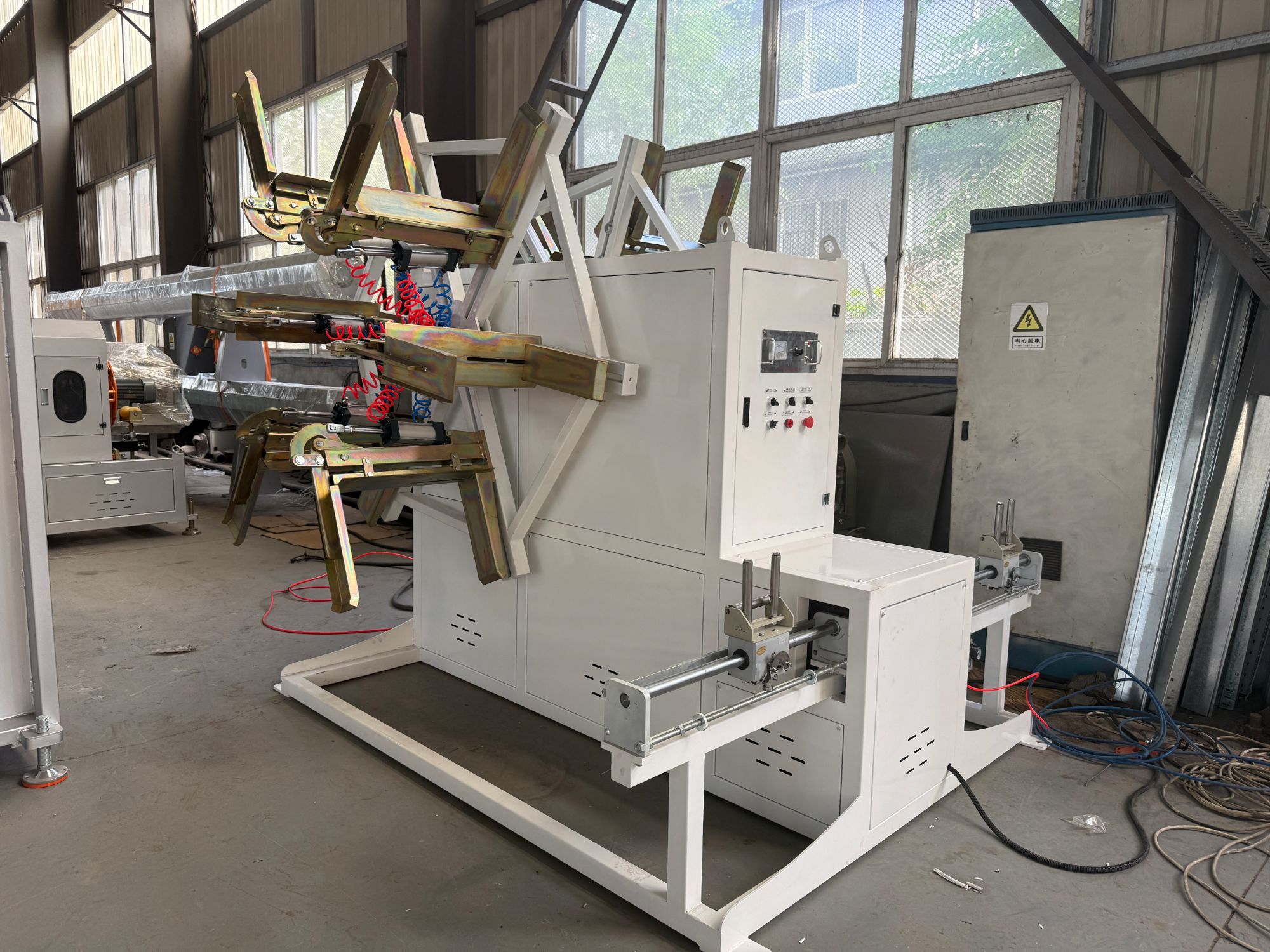
Output ratings on compressors and dryers often assume ideal ambient conditions, but real workshops rarely match those lab numbers. When cooling capacity isn't sized for the actual heat load, discharge temperatures climb, and the machine either trips on thermal overload or silently derates. The advertised CFM simply doesn't show up at the tool end.
Air-cooled heat exchangers lose efficiency as they ingest hot surrounding air, creating a feedback loop that further shrinks cooling performance. A unit labeled for 100% duty cycle might only sustain 70% output once the room temperature crosses 90°F. Without adequate cooling surface area or airflow, the compressor logic backs off motor speed or increases blowdown frequency, eroding the net air delivery.
The gap between claimed and actual output widens over time too. Dust, oil mist, and moisture fouling on cooler fins act as insulation, trapping heat in the compression circuit. Regular maintenance helps, but if the cooler was underspecified from the start, cleaning alone won't restore the missing CFM. True sustained output demands a cooling system that can reject the full heat of compression, not just pass a short factory test.
Vacuum Calibration and Wall Thickness Consistency from Start to Finish
In tube and profile extrusion, vacuum calibration doesn’t just set the outer diameter—it locks in the entire cooling path. A consistent negative pressure around the calibrator sleeve holds the hot melt against the gauge surface until the skin freezes. Any fluctuation here shows up later as ovality or thin spots.
Wall thickness drift often starts long before the calibration tank. Melt temperature swings, uneven screw output, or a worn mandrel can all shift material distribution. The vacuum only fixes what it touches; if the parison arrives uneven, even the best-calibrated sleeve can’t fully correct it. Operators who log vacuum level alongside haul-off speed and melt pressure tend to catch these shifts earlier.
From start to finish, the goal is repeatability. Once the initial sizing is set, small adjustments—like moving the vacuum rings slightly or swapping a sleeve with a different slot pattern—can tighten thickness tolerance without changing the entire line. Finished parts that hold a steady wall around the full circumference usually point back to a calibration setup that was tuned, not just turned on.
Real-Time Monitoring That Cuts Scrap Without False Alarms
In high-speed production lines, the difference between a good batch and a costly pile of scrap often comes down to milliseconds. Our monitoring system watches every critical parameter in real time—temperature, pressure, vibration, and dimensional drift—and flags genuine anomalies before they ruin a part. Because the algorithms learn the normal rhythm of each machine, they don't cry wolf over routine fluctuations. Operators finally get alerts they can trust, not a stream of nuisance warnings that get ignored.
False alarms are worse than no alarms at all: they train teams to hit snooze on real problems. We designed the detection logic to separate meaningful deviations from harmless noise, using adaptive thresholds tied to actual process capability. When a tool starts to wear or a coolant line begins to clog, the system catches the subtle shift early enough for a quick adjustment. The result is less material tossed in the bin, fewer unplanned stops, and a floor that runs calmer because everyone knows the alarm means something.
Rolling this out doesn't require a data science team. The unit hooks into existing sensors and PLCs, starts building its baseline within hours, and sends alerts to a phone, tablet, or dashboard. One injection molding plant reduced scrap from 4.2% to 1.1% in the first six weeks—not because operators changed their habits, but because they finally received precise, actionable signals instead of background noise. That is what quiet confidence on the line looks like.
Reducing Downtime with Quick Die Changes and Accessible Maintenance
Long die changeovers can quietly eat an entire shift before a single good part comes off the press. Teams often lose more time hunting for bolts, waiting on a crane, or shimming the die height than actually swapping tooling. Making the changeover quick starts with simple, repeatable setup steps: pre-set die heights, locating pins instead of eyeballed alignment, and hydraulic or quarter-turn clamps that eliminate dozens of wrench turns. When a die change drops from forty minutes to eight, the press stops being a bottleneck and starts acting like a flexible resource.
Accessible maintenance matters just as much as speed during the swap. If a lubrication point hides behind a guard that needs three tools to remove, it will get skipped until something squeals or seizes. Design choices like grouped grease fittings, sight glasses for oil level, and quick-release side panels turn routine checks into fifteen-second habits. Operators are far more likely to catch a worn guide bushing or a cracked spring when they can see it without crawling under the bolster. The goal is to put the most failure-prone items within arm's reach, so preventive care doesn't require a maintenance ticket.
The real downtime reduction happens when die changes and maintenance share the same rhythm. A two-minute visual check during each changeover can catch early wear on knockout bars, stripper plates, or cam surfaces before they become unplanned stops. Simple color-coded wear markers and a laminated checklist at the press keep the process honest without adding paperwork. Over time, the quick-change setup and accessible service points reinforce each other: faster swaps free up minutes for inspection, and easier inspection means fewer surprises that force an emergency die pull in the middle of a production run.
The Ten Production Lines That Earn Their Place in High-Uptime Plants
Most high-uptime plants end up with a handful of lines that rarely show up on the downtime report. These are the ones where the changeover procedure is written down, not passed around as tribal knowledge. They usually handle a stable product family and have fewer points where operators need to intervene. Because the workflow is repetitive, small deviations in cycle time or air pressure become noticeable before they turn into faults. Maintenance teams tend to keep these lines at the top of their calibration list, not out of habit, but because the machines reward attention with longer intervals between failures.
The lines that earn their place also share a certain mechanical honesty. They use fewer custom brackets, fewer odd-sized fittings, and more components that can be sourced from the local distributor. When a sensor fails, the replacement is on the shelf, not on backorder. Belt tensioners, gearboxes, and couplings are accessible without removing three other assemblies. This practicality extends to the control system as well. A line that shows a clear alarm code and points to the exact station beats one that triggers a generic fault and forces a technician to hunt with a laptop.
Another distinguishing feature is buffering. These lines rarely operate as a single brittle chain. Small accumulation zones between stations allow a brief jam or a slow operator response to be absorbed without stopping the upstream equipment. As a result, the line's output remains steady even when minor disruptions occur. Over time, this creates a self-reinforcing loop: the line is seen as reliable, so it receives better preventive care, which keeps it reliable. That reputation is not accidental. It comes from design choices that prioritize recoverability over raw speed.
FAQ
Look beyond motor power. The gearbox, screw design, and barrel wear resistance matter as much as peak RPM. A line with a 33:1 L/D barrier screw and a vacuum pump capacity matched to the melt output usually avoids surging. Also check whether the haul-off uses multiple caterpillar belts with individual torque control, because that's what keeps wall thickness steady at high speeds.
Many high-output lines use quick-change sizing units or vacuum tanks with segmented calibration sleeves. Instead of swapping entire tanks, operators can adjust the vacuum zones and water spray nozzles to match the new diameter, which cuts changeover time and keeps the line running near its rated output.
Grooved feed extruders combined with spiral mandrel dies have a noticeable effect. They allow higher screw speeds without melt fracture. Another underrated factor is the melt pump; adding a gear pump between the extruder and die stabilizes pressure and can lift output by 10–15% on the same screw.
Cooling is usually the real limit, not the extruder. Vacuum calibration with properly spaced spray rings removes heat fast enough to keep the pipe round and prevent sagging. If the cooling section is too short or the water temperature is not controlled within a few degrees, you either slow the line or accept higher ovality.
Often you can gain 10–20% by retrofitting a grooved barrel liner, a longer screw, or a larger die head—without replacing the whole line. But if the haul-off and cooling tanks are undersized, no extruder upgrade will help. Most plants get the best return by upgrading the downstream before touching the extruder.
Focus on screw and barrel wear measurement every 3,000 hours, not just visual checks. Also monitor vacuum pump oil and filter condition weekly; a weak vacuum directly affects wall thickness. Keep a log of melt pressure at a fixed screw speed—any upward drift means the screen pack or die gap needs attention.
Multi-layer lines can actually be more stable at high output because the outer layer can use a lower-viscosity resin that improves surface finish without affecting the core strength. The trade-off is more complex calibration, but once tuned they often run faster than a single-layer line making the same pressure rating.
Conclusion
Getting consistently high output from an HDPE pipe extrusion line rarely comes down to a single spec on a datasheet. The machines that hold up in real production share a few hard-won design choices. Screw geometry and melt temperature control matter enormously because pushing more kilograms per hour through the barrel only works if the melt stays homogeneous and free of hot spots. Plenty of lines claim impressive output figures, but without cooling capacity to match, those numbers fall apart in practice. You end up with pipe that sags, warps, or fails dimensional checks long before it reaches the haul-off. Vacuum calibration then has to step in and hold wall thickness steady from the very first meter to the last, and that demands more than a generic spray tank. It requires calibration sleeves, water flow, and vacuum levels that stay stable even as line speed changes. Real-time monitoring helps here, but it has to be tuned right: systems that cry wolf waste time, while sensors that ignore slow drift let bad product slip through.
Downtime is the other silent killer of throughput. Quick die changes and maintenance access that doesn't require a full teardown keep a line running when orders pile up. The best HDPE pipe lines are built around the idea that a shift change or a product switch should take minutes, not half a day. Among the top ten production lines that earn their place in high-uptime plants, you'll find a consistent pattern: balanced screw design, oversized cooling, precise vacuum calibration, monitoring that catches real problems without false stops, and mechanical layouts that respect the maintenance crew. These lines don't just hit a peak output number in a brochure; they hold reliable output week after week, which is what actually pays the bills in pipe manufacturing.
Contact Us
Contact Person: LISA LEE
Email: [email protected]
Tel/WhatsApp: +86 13780696467
Website: https://www.qdpipemachine.com